

Backstory
About a year ago I finally gave in and upgraded most of my lights to Philips Hue's. With the possibility to easily schedule when they should turn on and off, came the idea to also hookup the coffee maker and have the perfect wake up.
So in the evenings I top up with water and beans. And every morning my lights slowly turns on as the coffee simultaneously is being brewed. It's a pretty nice way to wake up. But there was one thing missing; my morning music!
My amplifier is a pretty dumb one and my first thought was to have a mechanical pusher, like SwitchBot. It seemed to do what I wanted, but after doing a little research, I found that they looked wonky and just the way they're attached with double sided tape, felt messy.
Then one day I wanted to listen to some music, I naturally reached for the remote (!!). I had been overthinking the whole thing. Now of course I could just buy a smart remote. But isn't that just the most boring thing!
Building the receiver
Before I could build a transmitter, I needed a receiver to decode all the messages sent by my amplifier's remote. As I couldn't find any documentation explaning the protocol used, or how an on/off-message looked.
Of course, the first thing I did was to order parts, who wants to do research anyways. Kidding aside. As I didn't know the correct frequency or even the protocol my amplifier used. I went ahead and ordered four different modules from Electrokit. Hoping that at least one them would work.
| Product No | Name |
|---|---|
| 40300098 | TSOP4830 IR-modul 30 kHz |
| 40300099 | TSOP4836 IR-modul 36 kHz |
| 40300101 | TSOP4840 IR-modul 40 kHz |
| 40300102 | TSOP4856 IR-modul 56 kHz |
The next thing was to research how an IR receiver actually works, and particular how to decode the packet sent by the remote.
I found that IR packets are made up of time based pulses. There's a base unit, a so called pulse length or pulse burst. It's usually the time elapsed between a rising and falling edge.

With this in mind, I wired up a simple circuit on a breadboard together with an Arduino and wrote some code that would print out a timestamp every time the signal rose or fell.

int inPin = 2;

void handle_interrupt() {
    Serial.println("Change at: " + String(micros()) + " us");
}

void setup() {
    Serial.begin(9600);
    pinMode(inPin, INPUT);
    attachInterrupt(digitalPinToInterrupt(inPin), handle_interrupt, CHANGE);
}
Of coursed it failed. Nothing! But I hadn't expected less, I changed out the IR receiver to the 36 kHz version. And would you know it. I aimed the remote and pressed a button. That gave me the following output:
Change at: 36232704 us
Change at: 36241796 us
Change at: 36246276 us
Change at: 36246884 us
Change at: 36247632 us
Change at: 36247968 us
Change at: 36248304 us
Change at: 36247616 us
This of course didn't tell my anything, just seven timestamps, no protocol matched that. I tried to guess which of the multiple protocols my remote used. At first I settled for RC-5 as that seemed to be a pretty common one, but it didn't changed the fact I only had got seven pulses. So instead of trying to decode faulty timestamps, I hooked up an oscilloscope to the data line.
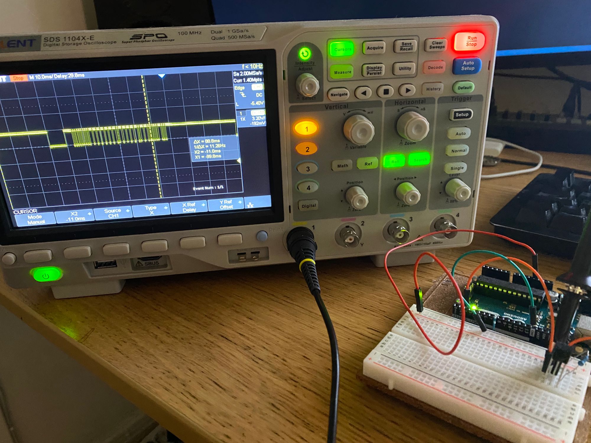
Now, I could clearly see the first pulse matching the NEC protocol, a 9 ms burst, followed by at least 50 other pulses. So it became clear that the code was at fault.
Rule of thumb: An interrupt handler should do as little work as possible. Because it halts all other execution and/or interrupts from happening. I made a guess that the printing somehow caused it to miss all the other interrupts. So I mapped each timestamp to an array.
volatile int changes_count = 0;
volatile unsigned long changes[300];
volatile unsigned long last_change = 0;

void handle_interrupt() {
    unsigned long now = micros();
    changes[changes_count++] = now;
    last_change = now;
}
And then I printed the results in the main Arduino loop function. With a print function, just to make it a bit more readable.
void print(int num, long time) {
  Serial.print(String(num + 1) + ") " + String(time) + "us\t" );
  if (num % 2)
    Serial.println();
}

void loop() {
  // At least one change and 100 ms should have passed without a change
  if (changes_count > 0 && (micros() - last_change) > 10000) {
    for (int i = 0; i < changes_count; i++) {
      long elapsed = changes[i + 1] - changes[i];
      print(i, elapsed);
    }

    // Clear everything for the next remote button press
    changes_count = 0;
    memset(changes, 0, sizeof(changes));
  }

  // Try to avoid jitter
  delay(10);
}
These are the results of a press on the on/off button.
1) 9112us	2) 4456us
3) 628us	4) 508us
5) 624us	6) 516us
7) 608us	8) 508us
...
61) 628us	62) 1628us
63) 624us	64) 512us
65) 624us	66) 512us
67) 608us	68) -361528us
With the first bit (position 1 and 2) being roughly 13.5 ms long. This is definitely the startbit from a remote controller using NEC. The second bit (position 3 and 4) is 1.125 ms long, so it should be a decoded as a zero. This looks really promising.
The NEC protocol
Now that we know that it is the NEC protocol we're a dealing with. How can we decode the packet?
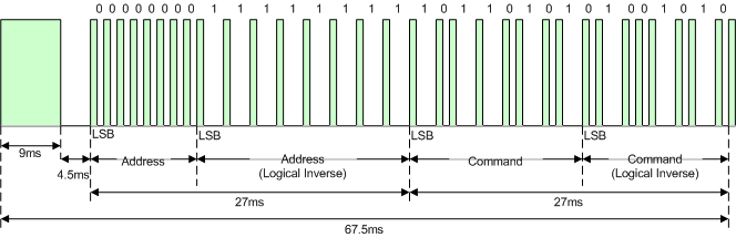
The protocol is made up of these parts
- 9 ms pulse
- 4.5 ms space
- 8 bit address
- 8 bit inverse address
- 8 bit command
- 8 bit inverse command
- 0.5 ms end pulse
A pulse width is 562.5 µs long. A logical zero is made of a pulse and a space, both a pulse width long, in total 1.125 ms. A logical one is 2.25 ms long, a pulse with double the space afterwards.
With this information it should be really easy to decode the message. Each bit is made up of the sum of two durations.
float duration = ((changes[i + 1] - changes[i]) + (changes[i + 2] - changes[i + 1])) / 1000.00;

if (duration >= 2) {
    return 1;
} else {
    return 0;
}One of the issues I ran into, the inverse address wasn't a perfect mirror of the address. It made me a bit (^ - ^) confused as the inverse command was correct; so the decoding should have worked.
It turns out there's an extended version of this protocol. Where the inverse address is just another 8 bit address, making the whole address space 16 bit. That's a lot of different remotes.
The Results
I've cleaned the code up a bit and also fixed the output to print the address and command in hex. And with that I'm now able to decode the message for on/off on my amplifier's remote. It also works with the CD-player.
Startbit: 13.57 ms - Startbit correct
Address: 0x00 0x7F, Command: 0xDF
Code repository https://github.com/sebek/smart-stereo
In the next part I will use the receiver to test the transmitter.